How to Connect Load Cells to Indicators
Posted by Taylor M. on Sep 18th 2026
If you maintain and service your own scales, you may need to replace a load cell or connect a new indicator to an existing scale. With a little knowledge about load cell wiring, you'll be able to connect any cell to an indicator like a pro.
It all starts with identifying the load cell wires.
Identify Load Cell Wires
To properly connect load cell cables, you must know the function of each colored wire and select the appropriate wire for each terminal connection in the indicator. Load cells typically come with four color coded wires (plus shield) but can have up to six (plus shield). Each colored wire will correspond to a different terminal connection. It is important to identify each wire and terminal connection correctly to prevent errors while connecting the wiring.
Let’s review the wires and their functions:
- Excitation Wires: Power the load cell’s internal Wheatstone bridge circuit
- Excitation+ (EXC+ or E+): Positive voltage to the load cell.
- Excitation- (EXC- or E-): Negative voltage or ground, completes the power circuit.
- Color Coded: Red and black
- Signal Wires: Carry the output signal from the load cell, the measured force or weight
- Signal+ (SIG+ or S+): Carries the positive side of the output signal, the force or weight measurement.
- Signal- (SIG- or S-): Carries the negative side of the output signal, balances the signal circuit.
- Color Coded: Green and white
- Sense Wires (optional): Monitor the voltage at the load cell and adjust for voltage drops over long cables
- Sense+ (Sense+): Positive voltage monitor connected to the Sense+ terminal of the indicator
- Sense- (Sense-): Negative voltage monitor connected to the Sense- terminal of the indicator
- Color Coded: Blue and yellow
- Shielding: Protects signal wires from electromagnetic interference (EMI) to maintain signal quality
- Bare wire or metal sheath surrounding others
RELATED ARTICLE: Types of Load Cell Cable
Connecting to Your Indicator
Follow these steps to connect a 4 and 6-wire load cell to an indicator:
- Identify the 6 Wires: The first step is selecting and preparing the appropriate cables. Remember, you can use the load cell datasheet or color code.
- Excitation+ (E+): 4 and 6-wire
- Excitation- (E-): 4 and 6-wire
- Signal+ (S+): 4 and 6-wire
- Signal- (S-): 4 and 6-wire
- Sense+ (Sen+ or Sense+): 6-wire only
- Sense- (Sen- or Sense-): 6-wire only
- Excitation Wires:
- Excitation+ (E+): Connect to the positive terminal of your power source or indicator
- Excitation- (E-): Connect to the ground/negative terminal of your power source or indicator
- Signal Wires:
- Signal+ (S+): Connect to the positive input terminal of your indicator or data acquisition system
- Signal- (S-): Connect to the negative input terminal of your indicator
- Sense Wires: (6-Wire Only)
- Sense+ (SEN+): Connect to the Sense+ (Sense+) terminal of the indicator
- Sense- (SEN-): Connect to the Sense- (Sense-) terminal of the indicator
- Check Connections:
- Verify that all wires are connected securely and match the manufacturer's load cell and indicator wiring diagram. This is critical for accurate readings. Incorrect wiring can cause errors like signal drifts, inaccurate reading results, or total signal loss.
- Ground the Shield (if applicable):
- To minimize the interference from external electrical signals, we recommend connecting the shield wire to the shielding terminal (sometimes marked SHLD or GND) in the indicator.
- Calibration:
- After completing the correct wiring, calibrate the device with known weights to ensure the indicator reads accurately. This step is essential for precision applications and allows you to adjust any potential errors. Follow your manufacturer’s guide to complete your calibration.
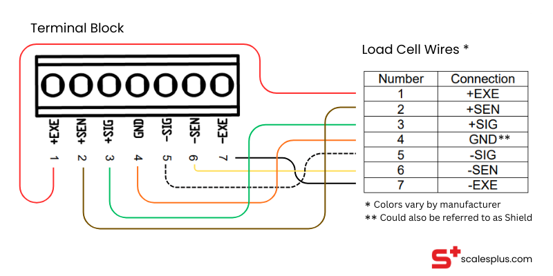
NOTE: Some indicators only have a terminal strip for a 4-wire connection. If you need to connect a 6-wire to this terminal, connect the EX+ and SEN+ wires together in the EX+ terminal connection spot. Then both EX- and SEN- wires int he EX- terminal connection spot.
Helpful Tips
Tips for accuracy and efficiency:
- Avoid Excessive Exposure: Don’t have excess wire exposed. This helps prevent grounding or interference
- Connect Securely: Connect each wire to its terminal securely to prevent signal loss or data corruption
- Color Codes: Follow the manufacturer’s color codes and wiring diagrams to avoid incorrect connections
- Shield: Ground the shield at the indicator end to block EMI